Connecting the DLPDLCR2000EVM projector kit to VisionSOM-6ULL: Difference between revisions
From SomLabs Wiki
Created page with "{{PageHeader|Connecting the DLPDLCR2000EVM projector kit to VisionSOM-6ULL}} __toc__ This tutorial shows how to prepare the system running on the VisionSOM-6ULL module and th..." |
No edit summary |
||
| (8 intermediate revisions by 2 users not shown) | |||
| Line 1: | Line 1: | ||
{{PageHeader|Connecting the DLPDLCR2000EVM projector kit to VisionSOM-6ULL}} __toc__ | {{PageHeader|Connecting the DLP (DLPDLCR2000EVM module) projector kit to VisionSOM-6ULL}} __toc__ | ||
This tutorial shows how to prepare the system running on the VisionSOM-6ULL module and the VisionCB-6ULL-STD carrier board to support the DLPDLCR2000EVM projector kit. The projector can be connected to the RGB LCD Connector of carrier board using an appropriate adapter. The | This tutorial shows how to prepare the system running on the VisionSOM-6ULL module and the VisionCB-6ULL-STD carrier board to support the DLPDLCR2000EVM projector kit. The projector can be connected to the RGB LCD Connector of carrier board using an appropriate adapter. The hardware design files are provided here: [[Media:SoMLabs-DLP-adapter.zip|SoMLabs-DLP-adapter.zip]]. | ||
[[File:www-DLP-ULL.jpg|center|800px]] | |||
[[File:www-DLP-modul.jpg|center|400px]] | |||
{{#evu:https://www.youtube.com/watch?v=UhNNCawvXYQ | |||
|alignment=center | |||
}} | |||
== Preparing the device tree file == | == Preparing the device tree file == | ||
| Line 47: | Line 55: | ||
After compilation, the new dtb file can be copied to the target system. | After compilation, the new dtb file can be copied to the target system. | ||
Configuring the system | == Configuring the system == | ||
The projector board requires some additional configuration and enabling using the I2C and GPIO interfaces. Setting the correct signal source and image resolution is | The projector board requires some additional configuration and enabling using the I2C and GPIO interfaces. Setting the correct signal source and image resolution is realized using the ''i2cset'' tool and the GPIO is controlled using the ''/sys/class/gpio'' subsystem: | ||
<pre> | <pre> | ||
| Line 60: | Line 68: | ||
</pre> | </pre> | ||
This configuration may be also written into an init.d script (/etc/init.d/projector) with permissions for execution: | This configuration may be also written into an ''init.d'' script (''/etc/init.d/projector'') with permissions for execution: | ||
<pre> | <pre> | ||
| Line 85: | Line 93: | ||
esac | esac | ||
exit 0 | exit 0 | ||
<pre> | </pre> | ||
<pre> | <pre> | ||
| Line 91: | Line 99: | ||
</pre> | </pre> | ||
In order to run the script automatically after boot, the update-rc.d needs also to be called: | In order to run the script automatically after boot, ''the update-rc.d'' needs also to be called: | ||
<pre> | <pre> | ||
update-rc.d projector defaults | update-rc.d projector defaults | ||
</pre> | </pre> | ||
Latest revision as of 12:00, 4 May 2020
Connecting the DLP (DLPDLCR2000EVM module) projector kit to VisionSOM-6ULL
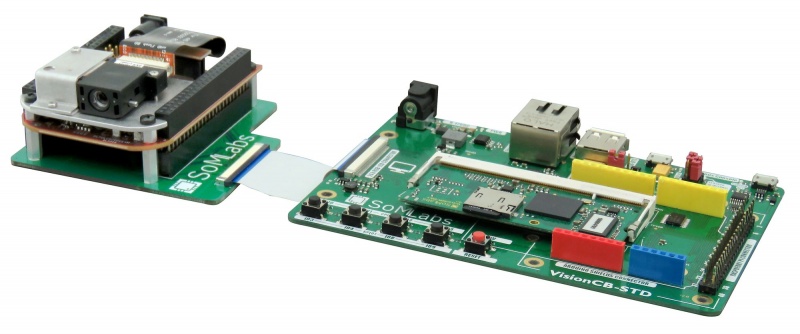
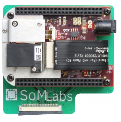
This tutorial shows how to prepare the system running on the VisionSOM-6ULL module and the VisionCB-6ULL-STD carrier board to support the DLPDLCR2000EVM projector kit. The projector can be connected to the RGB LCD Connector of carrier board using an appropriate adapter. The hardware design files are provided here: SoMLabs-DLP-adapter.zip.


{{#evu:https://www.youtube.com/watch?v=UhNNCawvXYQ |alignment=center }}
Preparing the device tree file
The example is based on the available Debian image. The device tree file can be modified according to this tutorial.
The projector module requires some changes of the timings used by the original system to support the parallel display interface. Changes need to be applied to the original somlabs-visionsom-6ull.dts file. The configuration of the LCDIF interface timings is shown below:
&lcdif {
		pinctrl-names = "default";
		pinctrl-0 = <&pinctrl_lcdif_dat
					 &pinctrl_lcdif_ctrl>;
		display = <&display0>;
		backlight = <&backlight_0>;
		status = "okay";

		display0: display {
				bits-per-pixel = <16>;
				bus-width = <24>;

				display-timings {
						native-mode = <&timing0>;
						timing0: timing0 {
						clock-frequency = <26000000>;
						hactive = <640>;
						vactive = <480>;
						hfront-porch = <14>;
						hback-porch = <12>;
						hsync-len = <4>;
						vback-porch = <9>;
						vfront-porch = <2>;
						vsync-len = <3>;

						hsync-active = <0>;
						vsync-active = <0>;
						de-active = <1>;
						pixelclk-active = <0>;
						};
				};
		};
};
After compilation, the new dtb file can be copied to the target system.
Configuring the system
The projector board requires some additional configuration and enabling using the I2C and GPIO interfaces. Setting the correct signal source and image resolution is realized using the i2cset tool and the GPIO is controlled using the /sys/class/gpio subsystem:
echo 1 > /sys/class/gpio/export
echo out > /sys/class/gpio/gpio1/direction
echo 1 > /sys/class/gpio/gpio1/value
i2cset -y 1 0x1b 0x0b 0x00 0x00 0x00 0x00 i
i2cset -y 1 0x1b 0x0c 0x00 0x00 0x00 0x07 i
i2cset -y 1 0x1b 0x0d 0x00 0x00 0x00 0x02 i
This configuration may be also written into an init.d script (/etc/init.d/projector) with permissions for execution:
#!/bin/sh
# /etc/init.d/projector: Configures the connected projector
### BEGIN INIT INFO
# Provides:          projector
# Required-Start:    $x11-common
# Required-Stop:     $x11-common
# Default-Start:     5
# Default-Stop:
# Short-Description: configures the projector I2C registers and gpio
### END INIT INFO

case $1 in
	start)
		echo 1 > /sys/class/gpio/export
		echo out > /sys/class/gpio/gpio1/direction
		echo 1 > /sys/class/gpio/gpio1/value
		i2cset -y 1 0x1b 0x0b 0x00 0x00 0x00 0x00 i
		i2cset -y 1 0x1b 0x0c 0x00 0x00 0x00 0x07 i
		i2cset -y 1 0x1b 0x0d 0x00 0x00 0x00 0x02 i
		;;
esac
exit 0
chmod a+x /etc/init.d/projector
In order to run the script automatically after boot, the update-rc.d needs also to be called:
update-rc.d projector defaults