How to flash VisionSOM-RT1176 Octal Flash memory: Difference between revisions
From SomLabs Wiki
Created page with "{{PageHeader|How to flash VisionSOM-RT1176 Octal Flash memory}} == Requirements == === Hardware === *VisionSOM-RT1176 module with Octal Flash ([https://somlabs.com/product/..." |
No edit summary |
||
| Line 25: | Line 25: | ||
== Flashing device using JLink == | == Flashing device using JLink == | ||
'''THE OCTAL FLASH VARIANT CAN ONLY BE PROGRAMMED WITH MICROCONTROLLER IN RECOVERY MODE (RCRV CONNECTED ON CARRIER BOARD)''' | |||
The JLink probe should be connected to the JTAG port on the catrrier board. Additionally the DAP/Cons uUSB port may be used in order to observe LPUART2 port output from PRINTF functions. Only the RX/TX pins should be connected: | The JLink probe should be connected to the JTAG port on the catrrier board. Additionally the DAP/Cons uUSB port may be used in order to observe LPUART2 port output from PRINTF functions. Only the RX/TX pins should be connected: | ||
Latest revision as of 12:32, 19 April 2024
How to flash VisionSOM-RT1176 Octal Flash memory
Requirements
Hardware
- VisionSOM-RT1176 module with Octal Flash (https://somlabs.com/product/visionsom-rt1170-sls14dual-core-arm-cortex-m7-cortex-m4/)
- VisionCB-RT1176-STD Carrier Board
- Segger J-Link interface (https://www.segger.com/products/debug-probes/j-link/)
Software
- xip files from the archive Xip_dcd_rt1172.zip
Configuring the project
The xip and dcd files from the Xip_dcd_rt1172.zip archive should be copied to the project sources. They contain the Flash memory configuration for execution in place (XIP) and DCD in order to configure SDRAM before application start.
The project should also contain the following symbols in project settings:
- XIP_BOOT_HEADER_ENABLE = 1
- XIP_BOOT_HEADER_DCD_ENABLE = 1
- BOARD_FLASH_SIZE = 0x4000000
- SL_OCTAL_FLASH = 1
Flashing device using JLink
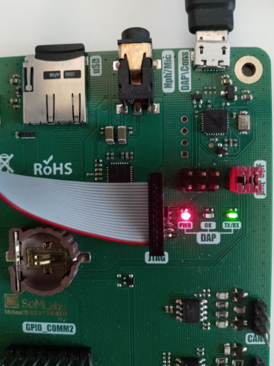
THE OCTAL FLASH VARIANT CAN ONLY BE PROGRAMMED WITH MICROCONTROLLER IN RECOVERY MODE (RCRV CONNECTED ON CARRIER BOARD)
The JLink probe should be connected to the JTAG port on the catrrier board. Additionally the DAP/Cons uUSB port may be used in order to observe LPUART2 port output from PRINTF functions. Only the RX/TX pins should be connected:

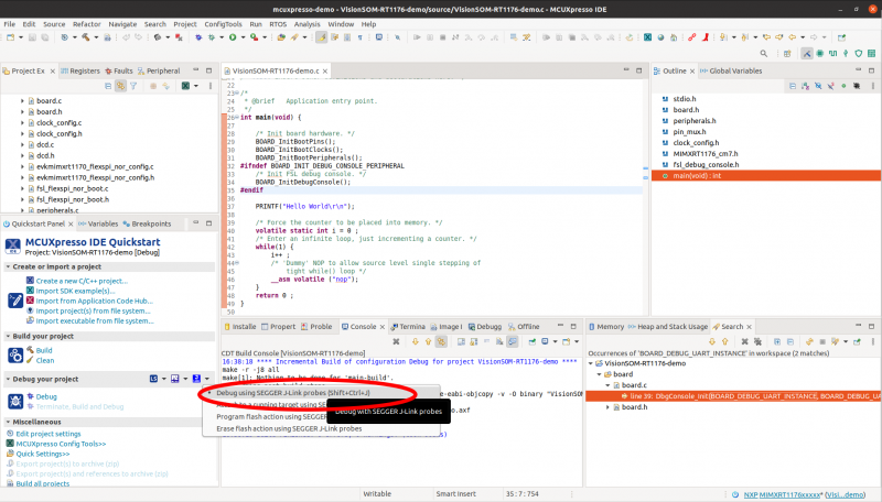
Te project may be flashed to a device directly using MCUXpresso.

Alternatively, the binary file may be programmed using JLinkExe tool with following script:
device MIMXRT1176XXX8_M7
si SWD
speed 4000
r
h
loadbin BINARY_FILE_NAME.bin 0x30000000
r
exit