SL-TFT7-TP-600-1024-LVDS Datasheet and Pinout
From SomLabs Wiki

Display module SL-TFT7-TP-600-1024-LVDS Datasheet and Pinout
General description

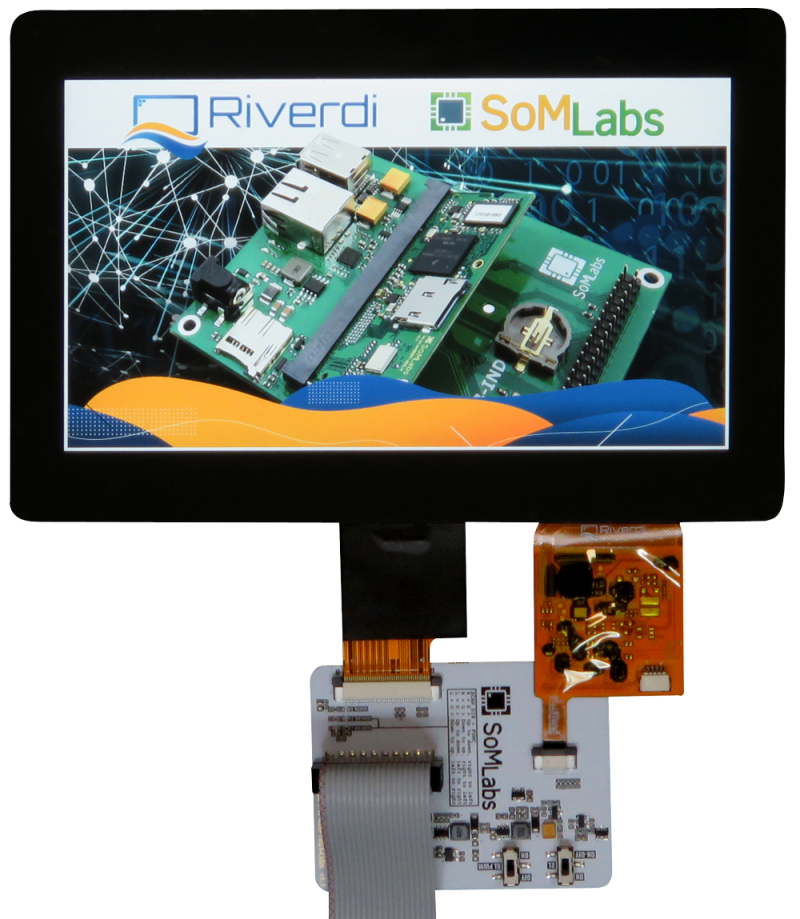
The SL-TFT7-TP-600-1024-LVDS is complete display TFT-LCD (1024x600 pixels) module integrated with capactive touch-panel. Module is powered from +5V @800mA (max.), the data interface is LVDS + I2C (for touch-panel controller). SL-TFT7-TP-600-1024-LVDS module is equipped with 22-pin flat cable (A-B), compatible with selected SoMLabs carrier-boards and video converters.
Features
- Powered by Riverdi RVT70HSLNWC00 TFT module covered with protective glass
- Intergated flexible signal cable
- Display size 7 inches
- Display LCD matrix 1024x600 px
- Capacitive touch-panel + TP controller
- LVDSinterface
- Single supply +5V (all necessary DC/DC converters are built-in)
- Backlight LEDs built-in
- Compatible with SoMLabs carrier boards equipped with LVDS video interface
Ordering info
SL-TFT7-TP-600-1024-LVDS - FPC 22-pin flat cable (A-B) is included.
Operating ranges
| Parameter | Value | Unit | Comment |
|---|---|---|---|
| Power Supply | - | ||
| Current | Maximum value, depends on displayed picture and backlight intensity | ||
| Video input voltage | |||
| Touch panel controller IO voltage | I2C interface, 2.2kΩ pull-up resistor on SDA and SCL lines | ||
| Environment temperature | oC | - |
Electrical parameters
| Signal name | Parameter | Value | Units | ||
|---|---|---|---|---|---|
| Min. | Typ. | Max. | |||
| +3.3V | Supply Voltage | 3.0 | 3.3 | 3.6 | V |
| - | Total Supply Current | 450 | 860 | 1290 | mA |
| VIO | Video IO Input Voltage | 0 | 3.3 | 3.6 | V |
| VTPIO | TP Controller IO Voltage | 0 | 3.3 | 3.6 | V |
| VPWREN | Power Enable Input Voltage | 0 | - | 3.3 | V |
| fTPI2C | TP Controller I2C Speed | - | - | 400 | kHz |
| fPWM | PWM Dimming Frequency | - | - | 1 | kHz |
| RINT | Interrupt Output Pull-up Resistance | - | 10 | - | kΩ |
| RPWREN | Power Enable Pull-up Resistance | - | 10 | - | kΩ |
| RTPI2C | Touch Panel Controller I2C IOs Pull-up Resistance | - | 2.2 | - | kΩ |
| fPWM | Recommended PWM signal frequency | 2 | 2.5 | 4 | kHz |
Pinout
IDC20 connector
| Connector pin | Function name | Description |
|---|---|---|
| 1 | +5V | Power supply |
| 2 | +5V | Power supply |
| 3 | PWREN1 | Backlight power enable input (10kOhm pull-down) |
| 4 | PWMIN2 | Backlight brightness input (PWM) |
| 5 | GND | - |
| 6 | GND | - |
| 7 | RXIN0- | Data lane 0 negative |
| 8 | RXIN0+ | Data lane 0 positive |
| 9 | RXIN1- | Data lane 1 negative |
| 10 | RXIN1+ | Data lane 1 positive |
| 11 | RXIN2- | Data lane 2 negative |
| 12 | RXIN2+ | Data lane 2 positive |
| 13 | GND | - |
| 14 | GND | - |
| 15 | RXCLK- | Data clock negative |
| 16 | RXCLK+ | Data clock positive |
| 17 | RXIN3- | Data lane 3 negative |
| 18 | RXIN3+ | Data lane 3 positive |
| 19 | TP_SCL | Touch panel controller SCL (2.2kOhm pull-up, TTL-LV) |
| 20 | TP_SDA | Touch panel controller SDA (2.2kOhm pull-up, TTL-LV) |
Note:
1. PWREN is external signal input that can be disconnected from DC/DC converter with on-board switch (vide section Switches)
2. PWMIN is external signal input that can be disconnected from DC/DC converter with on-board switch (vide section Switches)
3. Signal TP_INT is not available in the connector IDC20. In some cases touch-panel controller may not work properly.
4. Connector IDC20 is compatible with IDC18 connector of MIPI-DSI/LVDS converter (SL-MIPI-LVDS-HDMI-CNV), excluding pins 19 and 20 (touch-panel controller I2C interface).
FPC22 connector
| Connector pin | Function name | Description |
|---|---|---|
| 1 | GND | - |
| 2 | RXIN0- | Data lane 0 negative |
| 3 | RXIN0+ | Data lane 0 positive |
| 4 | GND | - |
| 5 | RXIN1- | Data lane 1 negative |
| 6 | RXIN1+ | Data lane 1 positive |
| 7 | GND | - |
| 8 | RXIN2- | Data lane 2 negative |
| 9 | RXIN2+ | Data lane 2 positive |
| 10 | GND | - |
| 11 | RXCLK- | Data clock negative |
| 12 | RXCLK+ | Data clock positive |
| 13 | GND | - |
| 14 | RXIN3- | Data lane 3 negative |
| 15 | RXIN3+ | Data lane 3 positive |
| 16 | PWREN1 | Backlight power enable input (10kOhm pull-down) |
| 17 | PWMIN2 | Backlight brightness input (PWM) |
| 18 | TP_INT | Touch panel interrupt (10kOhm pull-up, TTL-LV) |
| 19 | TP_SCL | Touch panel controller SCL (2.2kOhm pull-up, TTL-LV) |
| 20 | TP_SDA | Touch panel controller SDA (2.2kOhm pull-up, TTL-LV) |
| 21 | +5V | Power supply |
| 22 | +5V | Power supply |
Note:
1. PWREN is external signal input that can be disconnected from DC/DC converter with on-board switch (vide section Switches)
2. PWMIN is external signal input that can be disconnected from DC/DC converter with on-board switch (vide section Switches)
Switches

Note:
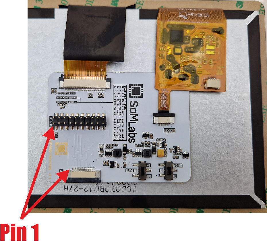
1. Switch marked BL allows to control on-board backlight DC/DC converter: LEDs can be on permanently (position ON) or cotrolled by logic state of PWREN signal (position ON-OFF, ON if PWREN=1 and OFF if PWREN=0)
2. Switch marked BL PWM allows to change backlight brightness using external PWM signal connected to PWMIN signal. Recommended PWM frequency >=2kHz.
Hardware configuration options

Note:
1. Switch marked BL allows to control on-board backlight DC/DC converter: LEDs can be on permanently (position ON) or cotrolled by logic state of PWREN signal (position ON-OFF, ON if PWREN=1 and OFF if PWREN=0)
2. Switch marked BL PWM allows to change backlight brightness using external PWM signal connected to PWMIN signal. Recommended PWM frequency >=2kHz.
