TitanSBC-8Mmini Datasheet and Pinout
From SomLabs Wiki

TitanSBC-8Mmini Datasheet and Pinout
General description

The TitanSBC-8Mmini (SLC5) is a new generation single board computer (SBC), based on energy efficient and fast 64-bit quad core industrial, heterogenous MPU NXP i.MX8Mmini, equipped with Cortex-A53 cores.
The main MPU of TitanSBC-8Mmini is equippped with real-time Cortex-M4 core, Gigabit Ethernet interface, video codec (H.265, H.264, VP8, VP9), PCIe 2.0 interface and another communication peripherals often used in industrial applications. Internal GPU offers up to 1080p60 resolution on HDMI interfaces with independent 2D (GC320) and 3D (Vivante GCNano Ultra) GPU engines. The MPU cores run at 1.8GHz without thermal throttling using the stock heat sink allowing a robust and quiet computer. The low-power LPDDR4 RAM memory used by default in TitanSBC-8Mmini computer additionally helps save energy.
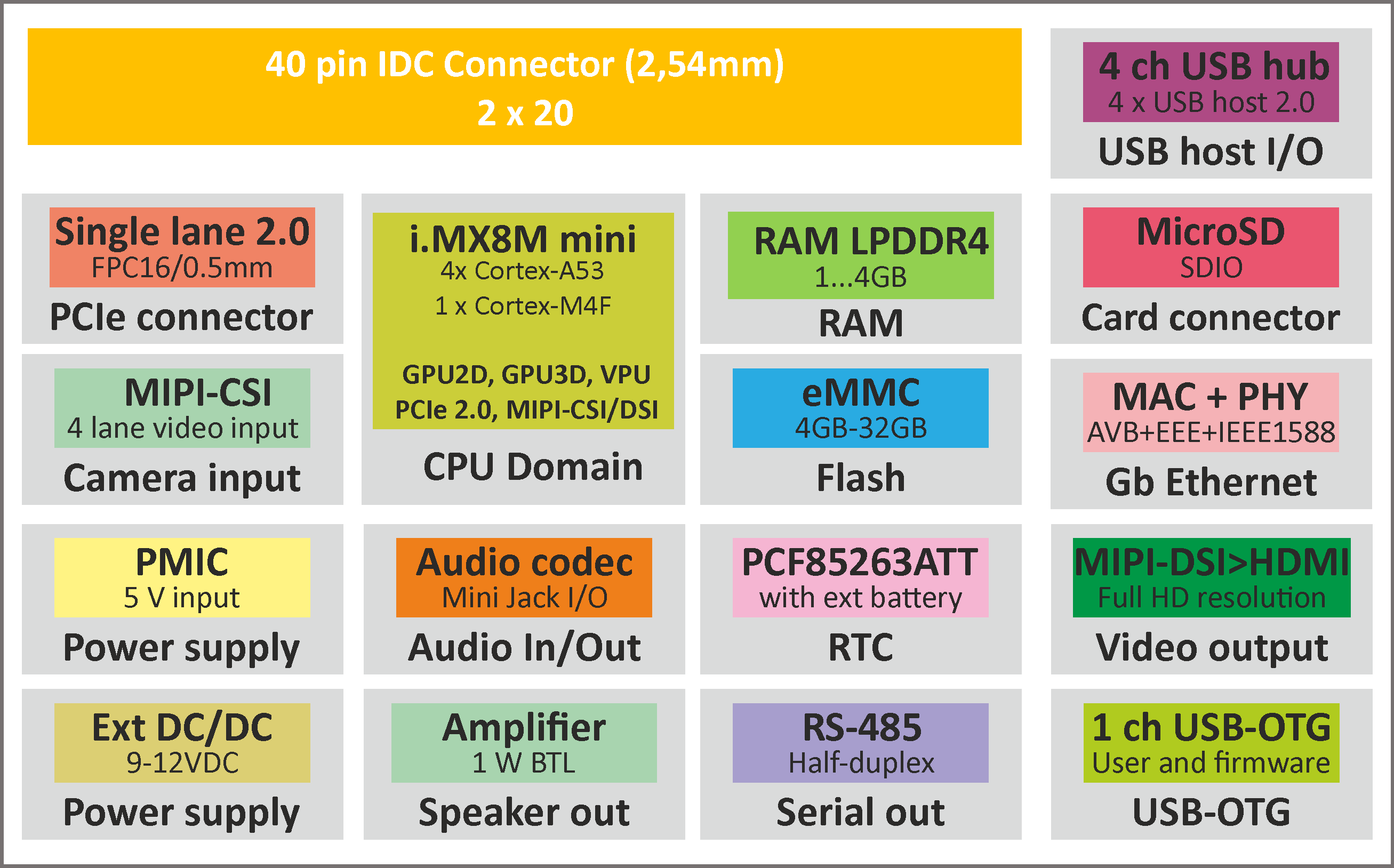
The TitanSBC-8Mmini is equipped with on-board 1Gb/s Ethernet interface, half-duplex RS-485 interface, on-board RTC with external battery connector, audio codec (with headphone and microphone Jack connector and external speakers outputs), HDMI, 4 x USB 2.0 host connectors, 1 x USB-OTG connector, MIPI-CSI camera connector, PCIe 2.0 FPC connector (dedicated M.2 adapter available: SL-ADP-PCIe-M2), MicroSD card connector, DC/DC converter adapted to 12V external power supply.
Additionally the TitanSBC-8Mmini SBC is equipped with easy to use 2×20 pin connectors with 28 GPIOs for any use in user application.
The StarSBC-6ULL supports industrial grade embedded applications.
Applications
- Multimedia Interfaces
- Home Control Panels
- Industrial HMI
- Industrial Controls
- Home Security and Surveillance
- Edge Computing
- IoT Sensor Hubs
- Home Appliances
- Home Automation – Smart Home
- Robotic Appliance
- Transport Ticketing
- Smart Lighting
- Point-of-sales (POS) terminals
- Cash Register
- Smart grid infrastructure
- Outdoor equipment
Features
- Powered by quad-core heterogenous NXP i.MX8Mmini (Cortex-A53 + Cortex-M4) application processor
- Core clock up to 1.8GHz
- Up to 4GB LPDDR4
- Up to 32GB eMMC
- HDMI video output (3D + 2D GPUs, full HD resolution)
- Single MIPI-CSI camera input
- Half-duplex RS-485 interface on-board
- 10/100/1000 Ethernet PHY on-board
- 4 x USB 2.0 (host) + USB-OTG interfaces
- PCIe 2.0 connector (FPC, 16 pin, 0.5 mm)
- Stereo audio codec (headphone, microphone and speakres connectors)
- Power-efficient and cost-optimized solution
- Ideal for industrial IoT and embedded applications
- Integrated security features
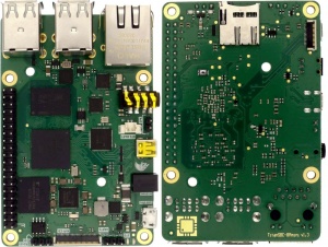
Pictures of SBC versions
| Version | Photo |
|---|---|
| eMMC |
 |
Ordering info
| SLC | Product type SLC - Single Board Computer |
| N | Form factor 5 - TitanSBC |
| X8MMQC | CPU Family X8MM - NXP i.MX8Mmini |
| CpuType | CPU Type QC - Fully featured: 4 x Cortex-A53, 1 x Cortex-M4, GPU3D, video codec |
| Clock | CPU Clock Speed 1600C - 1.6GHz 1800C - 1.8GHz |
| RamSize | LPDDR4 RAM Size 01GR - 1GB 02GR - 2GB 04GR - 4GB |
| FlashSize | Flash Size Type and Density 04GE - 4GB eMMC 08GE - 8GB eMMC 16GE - 16GB eMMC 32GE - 32GB eMMC |
| SF | Special Features 0SF - Fully equipped |
| TEMP | Operating Temperature C - Consumer: 0 to +70 C E - Extended: -25 to +70 C I - Industrial: -40 to +85 C |
Block Diagram

Operating ranges
| Parameter | Value | Unit | Comment |
|---|---|---|---|
| Power Supply | Connected to J100 or J101 or USB conenctors1 | ||
| GPIO voltage | - | ||
| Environment temperature2 | oC | Industrial range w/o WiFi module | |
| Industrial (extended) range with WiFi module | |||
| Consumer range |
Note:
1. Power supply can be delivered by two ways: J100/J101 or MicroUSB (OTG).
2. Maximum MPU junction temperature is +105oC (industrial version) or +95oC (consumer version).
Electrical parameters
| SBC signal name |
Parameter | Value | Units | ||
|---|---|---|---|---|---|
| Min. | Typ. | Max. | |||
| +5V | SBC supply voltage1 | 4.85 | 5 | 5.15 | V |
| +3.3VO | Supply voltage for external peripherals | 3.2 | 3.3 | 3.35 | V |
| VGPIO | GPIO Input Voltage | 0 | 3.3 | 3.62 | V |
| I+5V | Total Supply Current | TBD | TBD | TBD | mA |
| I+3.3VO | Output current of 3.3V power supply for peripherals |
- | - | 0.1 | A |
| VBATT | RTC/SNVS Backup Battery Supply |
2.66 | - | 3.6 | V |
Notes:
1. The external voltage connected to pin 2 of J100 and/or J101 or MicroUSB.
2. Applying the maximum voltage 3.6V results in shorten lifetime. Recommended value is smaller than 3.5V.
Features

| Connector pin number | Default function | GPIO | Ball numer BGA289 | Notes |
|---|---|---|---|---|
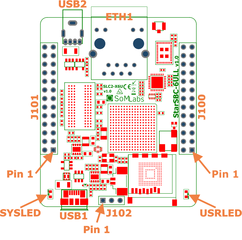
| J100 | ||||
| 1 | +3,3VO | +3,3V power output (max. 100 mA) - paralelly connected to pin 1 of J101 | ||
| 2 | +5V | External power supply (power source) 5V - paralelly connected to pin 2 of J101 | ||
| 3 | UART8-RXD | ENET2_TX_EN | B15 | |
| 4 | GND | |||
| 5 | UART8-TXD | ENET2_TX_DATA1 | A16 | |
| 6 | UART3-TXD | UART3_TX_DATA | H17 | |
| 7 | PWM5 | LED_DATA18 | A13 | |
| 8 | UART3-RXD | UART3_RX_DATA | H16 | |
| 9 | GND | |||
| 10 | UART3-CTS | UART3_CTS | H15 | |
| 11 | UART4-RXD | LCD_ENABLE | B8 | |
| 12 | UART3-RTS | UART3_RTS | G14 | |
| 13 | UART4-TXD | LCD_CLK | A8 | |
| 14 | GND | |||
| 15 | I2C4-SDA | LCD_DATA02 | E10 | In I2C mode external pull-up resistor is necessary (no any internal pull-up) |
| 16 | I2C3-SDA | LCD_DATA00 | B9 | In I2C mode external pull-up resistor is necessary (no any internal pull-up) |
| 17 | I2C4-SCL | LCD_DATA03 | D10 | In I2C mode external pull-up resistor is necessary (no any internal pull-up) |
| 18 | I2C3-SCL | LCD_DATA01 | A9 | In I2C mode external pull-up resistor is necessary (no any internal pull-up) |
| 19 | ECSPI2-MOSI | UART5_TX_DATA | F17 | |
| 20 | UART7-RXD | LCD_DATA16 | C13 | |
| 21 | ECSPI2-MISO | UART5_RX_DATA | G13 | |
| 22 | UART7-TXD | LCD_DATA17 | B13 | |
| 23 | ECSPI2-SCLK | UART4_TX_DATA | G17 | |
| 24 | UART7-CTS | LCD_DATA07 | D11 | |
| 25 | ECSPI2-CS | UART4_RX_DATA | G16 | |
| 26 | UART7-RTS | LCD_DATA06 | A10 | |
| J101 | ||||
| 1 | +3,3VO | +3,3V power output (max. 100 mA) - paralelly connected to pin 1 of J100 | ||
| 2 | +5V | External power supply (power source) 5V - paralelly connected to pin 2 of J100 | ||
| 3 | USB1-DP | Line connected to USB1 channel through MUX (output ENET2_RX_ER, ball D16 is USB1 connection selector). Connected to USB1-DP MPU line if ENET2_RX_ER="0" (USB1-SEL), in another case USB1-DP MPU line is connected to MicroUSB connector (USB-OTG). | ||
| 4 | GND | |||
| 5 | USB1-DM | Line connected to USB1 channel through MUX (output ENET2_RX_ER, ball D16 is USB1 connection selector). Connected to USB1-DM MPU line if ENET2_RX_ER="0" (USB1-SEL), in another case USB1-DM MPU line is connected to MicroUSB connector (USB-OTG). | ||
| 6 | GPIO-6 | GPIO1_IO06 | K17 | |
| 7 | GPIO3.17 | LCD_DATA12 | C12 | |
| 8 | GPIO-7 | GPIO1_IO07 | L16 | |
| 9 | GND | |||
| 10 | GPIO-8 | GPIO1_IO08 | N17 | |
| 11 | CAN1-TX | LCD_DATA08 | B11 | |
| 12 | GPIO-9 | GPIO1_IO09 | M15 | |
| 13 | CAN1-RX | LCD_DATA09 | A11 | |
| 14 | GND | |||
| 15 | CAN2-TX | LCD_DATA10 | E12 | |
| 16 | GPIO3.2 | LCD_HSYNC | D9 | |
| 17 | CAN2-RX | LCD_DATA11 | D12 | |
| 18 | GPIO3.3 | LCD_VSYNC | C9 | |
| 19 | MQS-R | LCD_DATA22 | A14 | |
| 20 | UART2-RXD | UART2_RX_DATA | J16 | |
| 21 | MQS-L | LCD_DATA23 | B16 | |
| 22 | UART2-TXD | UART2_TX_DATA | J17 | |
| 23 | GPIO3.25 | LCD_DATA20 | C14 | |
| 24 | UART2-CTS | UART2_CTS | J15 | |
| 25 | GPIO3.26 | LCD_DATA21 | B14 | |
| 26 | UART2-RTS | UART2_RTS | H14 | |
| J102 | ||||
| 1 | UART1-TXD | UART1_TX_DATA | K14 | TxD line of Linux console port (LV-TTL logic levels) |
| 2 | UART1-RXD | UART1_RX_DATA | K16 | RxD line of Linux console port (LV-TTL logic levels) |
| 3 | GND | |||
| Another functions | ||||
| BUZZER | GPIO1_IO05 | M17 | Electromagnetic speaker control output (thru NPN driver) | |
| SYSLED | ENET2_TX_CLK | D17 | System or user LED control output (heartbeat by default, thru NPN driver) | |
| USRLED | LCD_DATA14 | A12 | User LED control output (thru NPN driver) | |
| WDOG-B | LCD_RESET | E9 | Used by system, do not modify default configuration | |
| ENET-MDIO | ENET2_RX_DATA0 | C17 | ||
| ENET-MDC | ENET2_RX_DATA1 | C16 | ||
| ENET1-RST | ENET2_RX_EN | B17 | ||
| ENET1-INT | ENET2_TX_DATA0 | A15 | ||
| USB1-SEL | ENET2_RX_ER | D16 | ||
| USB1-ID | GPIO1_IO00 | K13 | ||
| USB1-VBUS-OC | GPIO1_IO01 | L15 | ||
| USB1-VBUS-EN | GPIO1_IO04 | M16 | ||
| USB2-VBUS-OC | GPIO1_IO03 | L17 | ||
| USB2-VBUS-EN | GPIO1_IO02 | L14 | ||
| WiFi and BLE module connection | ||||
| BT-ENABLE | CSI_MCLK | F5 | ||
| WLAN-HWAKE | CSI_PIXCLK | E5 | ||
| BT-HWAKE | CSI_VSYNC | F2 | ||
| BT-WAKE | CSI_HSYNC | F3 | ||
| BT-RXD | CSI_DATA00 | E4 | UART5 | |
| BT-TXD | CSI_DATA01 | E3 | UART5 | |
| BT-RTS | CSI_DATA02 | E2 | UART5 | |
| BT-RTS | CSI_DATA03 | E1 | UART5 | |
| BT-PCM-SYNC | CSI_DATA04 | D4 | ||
| BT-PCM-CLK | CSI_DATA05 | D3 | ||
| BT-PCM-OUT | CSI_DATA06 | D2 | ||
| BT-PCM-IN | CSI_DATA07 | D1 | ||
| CLK32kHz | JTAG_CTK | M14 | Clock output to 1DX radio module (WiFi/BLE) | |
| JTAG_MOD | JTAG_MOD | P15 | Permanently connected to GND | |
| BOOT_MODE1 | BOOT_MODE1 | U10 | Permanently connected to GND | |
Note:
1. WiFi radio module is connected to SDIO1 interface.
2. Power supply (5V) for SBC can be connected to pin 2 of J100 or 101 or MicroUSB connector.
Software loading - BOOT0 jumper
If BOOT0 jumper is open - MPU starts normally (software from MMC memory is loading).
If pins of BOOT0 jumper are connected to each other, bootloader starts (active on USB1).