How to interface NXP FXAS2100X gyroscope with the VisionSOM-6ULL
From SomLabs Wiki
How to interface NXP FXAS2100X gyroscope with the VisionSOM-6ULL
Description
FXAS2100x is a triple-axis digital gyroscope with 16-bit resolution and adjustable range from 250°/s to 2000°/s, and up to 800 Hz sample rate. In the example, we will use the FRDM-STBC-AGM01 module to show how to communicate with this sensor on the I²C bus.

Prerequisites
This tutorial is based on a pre-prepared image for VisionSOM-6ULL module. The image is available here: Ready-to-use card image for the example.
For more info how to prepare SD Card with Debian 9.2 for VisionSOM-6ULL on Windows, please visit How to prepare SD Card with Debian 9.2 for VisionSOM-6ULL on Windows. Please remeber to use a proper image file: Ready-to-use card image for the example.
| In the ready-to-use OS image, the kernel driver for the gyroscope has already been enabled in the kernel config, and the device has been added to the devicetree. |
If you want to enable the sensor's driver in the kernel by yourself, the following options have to be selected:
Device Drivers  --->
	Misc devices  --->
		<*> Freescale FXAS2100X gyroscope sensor
The gyroscope needs to be declared in the devicetree:
&i2c2 {
    status = "okay";
    fxas2100x@20 {
         compatible = "fsl,fxas2100x";
         reg = <0x20>;
      };
};
For more info how to customize, build and upload Device Tree file, please visit How to customize Debian 9.2 device tree.
Hardware set-up
| Do not connect the shield to the Arduino-style connector on VisionCB. The connector on VisionCB has a 5V supply and uses 5V logic. The shield accepts only 3.3V. |
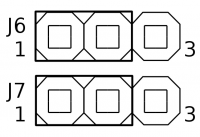
Firstly, make sure the jumpers J6 and J7 are both set to positions 1-2:

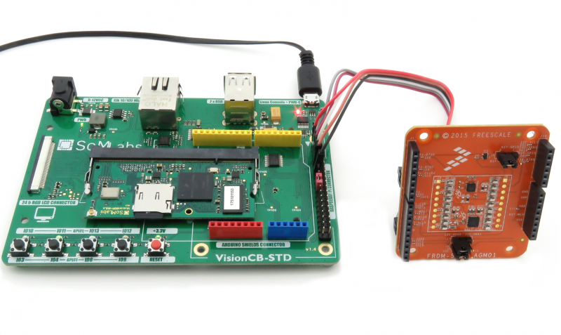
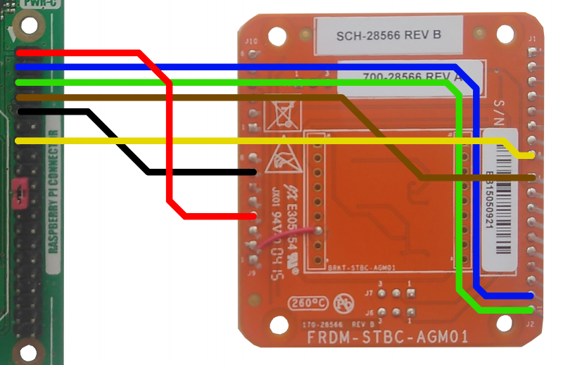
Connect the FRDM-STBC-AGM01 module according to the photo below:

Reading the values
To run the gyroscope, you need to enable it:
root@localhost:~# cd fxas2100x
root@localhost:~/fxas2100x# ./fxas2100x_enable.sh
[ 1470.052799] misc FreescaleGyroscope: mma enable setting active
and then, you should build and run the test application:
root@localhost:~/fxas2100x# make
make: Warning: File 'Makefile' has modification time 2963329 s in the future
cc -Wall -O0 -g -funsigned-char -I.  -c fxas2100x.c -o fxas2100x.o
cc -g -O0 -Wl,--gc-sections,--relax -L/usr/local/lib -lnfc_nci_linux -lpthread fxas2100x.o -o gyro-i2c
make: warning:  Clock skew detected.  Your build may be incomplete.
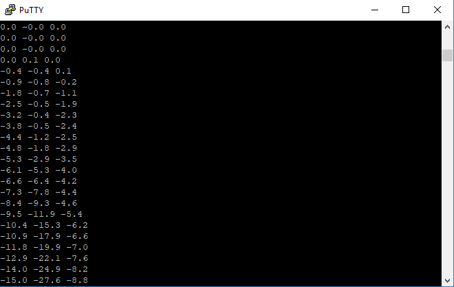
Now, it's time to run the application. The readings of three axis values will be displayed after executing:
root@localhost:~/fxas2100x# ./gyro-i2c
0.0 0.0 0.0
0.1 0.0 -3.0
-0.3 0.3 -6.9
^C
root@localhost:~/fxas2100x#
Any move of the sensor board will be related with the readings changes:
