How to create and run the first FreeRTOS application on the VisionSOM-RT1176
From SomLabs Wiki
How to create and run the first FreeRTOS application on the VisionSOM-RT1176
This article describes how to create and run first FreeRTOS application on the VisionSOM-RT1176 module with the NXP i.MX RT1176 microcontroller. The application will be executed from the external QSPI or Octal Flash memory.
Contents
Requirements
Hardware
- VisionSOM-RT1176 module (https://somlabs.com/product/visionsom-rt1170-sls14dual-core-arm-cortex-m7-cortex-m4/)
- VisionCB-RT1176-STD Carrier Board
- Segger J-Link interface (https://www.segger.com/products/debug-probes/j-link/)
Software
- MCUXpresso IDE – this tutorial was prepared for the version 11.9.0
- The MCUXpresso comes with the SEGGER drivers, however on some systems a driver update may be required: https://www.segger.com/downloads/jlink#J-LinkSoftwareAndDocumentationPack
- SDK – the SDK needs to be generated for the i.MX RT1176 microcontroller and should contain the FreeRTOS system. More information: https://mcuxpresso.nxp.com/en/welcome
Importing the SDK
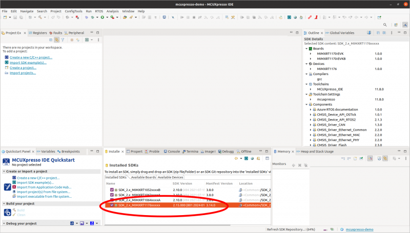
The created SDK needs to be imported to the MCUXpresso IDE. We can do it by selecting the import archive option in the Installed SDKs window, or by simple drag-and drop the archive file to this window.
Generating a new project
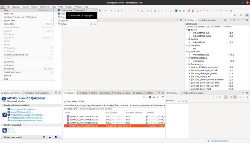
The MCUXpresso contains a project creator tool that allows to configure a new project with the software components available in the imported SDKs. The project creator is available in the File menu (File→New→Project…).
The project appropriate type is the C/C++ Project.
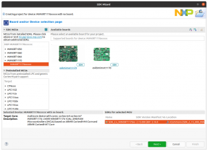
Next, a target microcontroller should be selected (without selecting any evaluation board).
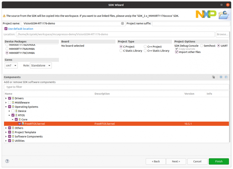
In the next window we can set the name of the project, select core, the device package and the required software components and drivers. All required drivers are already selected by default (including GPIO and LPUART), however we need to add FreeRTOS operating system.
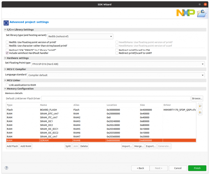
In the next window we can configure the C library and the compiler options. This window also contains the available memories, so we need to define the Flash memory (Location 0x30000000; Driver MIMXRT1050_SFDP_QSPI.cfx) and external SDRAM (Location 0x80000000). The remaining parameters in this window may be configured with their default values.
After this step the project files should be created, but before we can compile it two more steps are required for proper Flash and SDRAM configuration. In order to execute the code directly from Flash and use SDRAM memory we need to add xip and dcd source files that are available in the following archive.
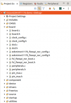
We can copy all xip and dcd files to the board directory.
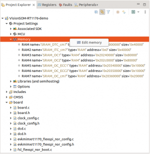
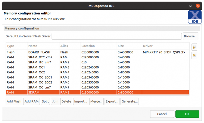
In case the board Flash and SDRAM has not beed properly set we can do it using memory settings.
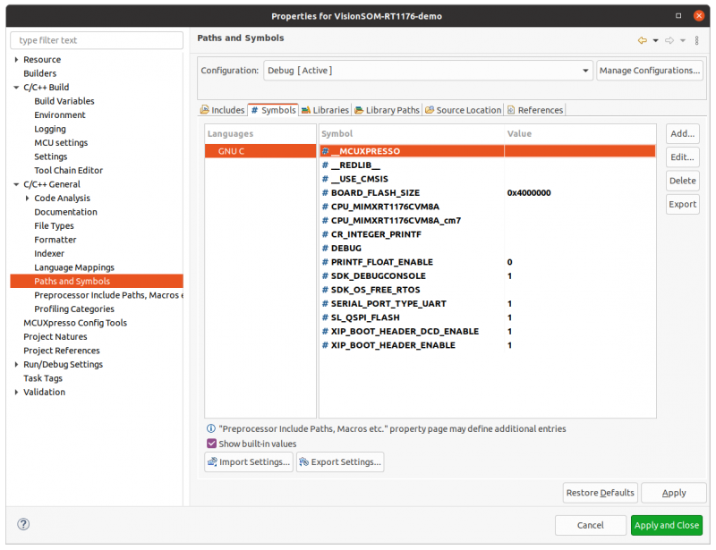
Finally we need to set a couple of symbols in project settings. The settings window can be opened by right-cliking on the project name and selecting Settings from the list. In C/C++ General -> Paths and Symbols -> Symbols dialog, the following symbols should be defined:
- XIP_BOOT_HEADER_ENABLE = 1
- XIP_BOOT_HEADER_DCD_ENABLE = 1
- BOARD_FLASH_SIZE = 0x4000000
One of the folling symbols should also be added according to the Flash memory type present on board.
- SL_QSPI_FLASH = 1
- SL_OCTAL_FLASH = 1
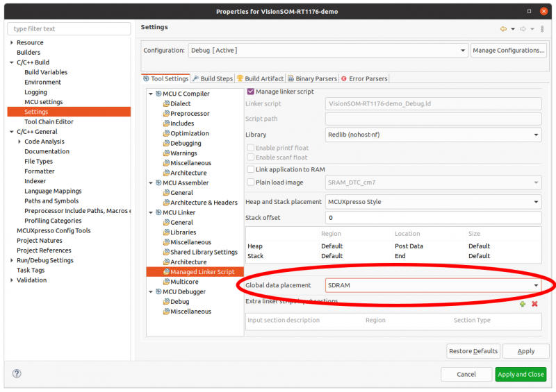
We can also select one of the RAM memories for program data placement. It can be done in the settings window C/C++ Build -> Settings -> Tool Settings -> MCU Linker -> Global data placement.
Configuring LPUART and GPIO
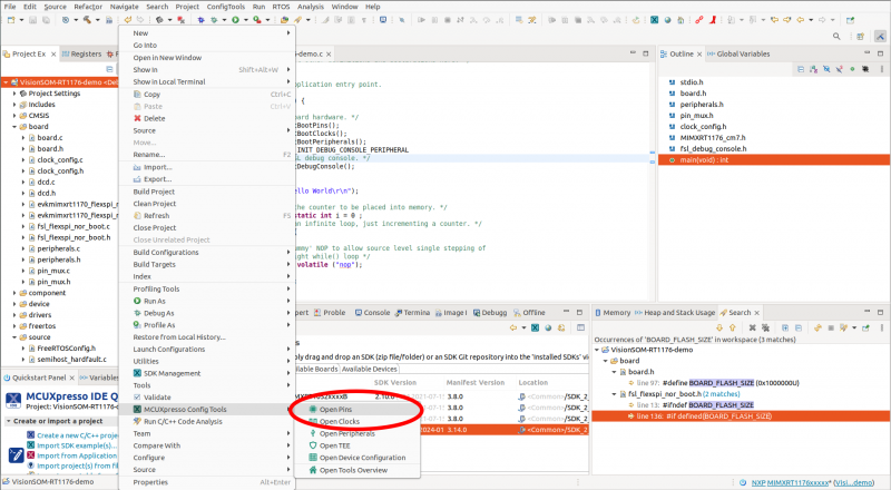
In the demo example we use LPUART and GPIO, so we need to configure processor pads for appropriate functions. For this we will use the MCUXpresso Config Tools that mey be also used for peripherals and clock configuration. The tools can be opened by right-clicking project name and selecting MCUXpresso Config Tools -> Open Pins.
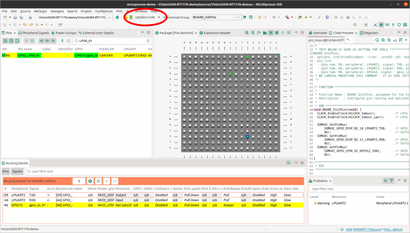
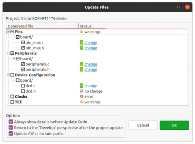
We need to configure three pads and generate the initialization code by selecting Update Code button.
- LPUART
- IOMUXC_GPIO_DISP_B2_10_LPUART2_TXD
- IOMUXC_GPIO_DISP_B2_11_LPUART2_RXD
- GPIO
- IOMUXC_GPIO_LPSR_01_GPIO12_IO01
The dcd.* files should not be updated.
Finally we should modify the automatically generated macros for LPUART and GPIO in board.h file:
- define DEBUG_CONSOLE_UART_INDEX 2
- define BOARD_USER_LED_GPIO GPIO12
- define BOARD_USER_LED_GPIO_PIN (1U)
And remove the flash size redefinition
- define BOARD_FLASH_SIZE (0x1000000U)
Flashing device using JLink
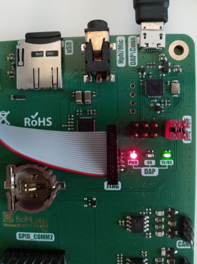
We can now build the project and program Flash memory using JLink debugger. The JLink probe should be connected to the JTAG port on the catrrier board. Additionally we can connect the DAP/Cons uUSB port to the PC in order to observe LPUART2 port output from PRINTF functions. Only the RX/TX pins should be connected:
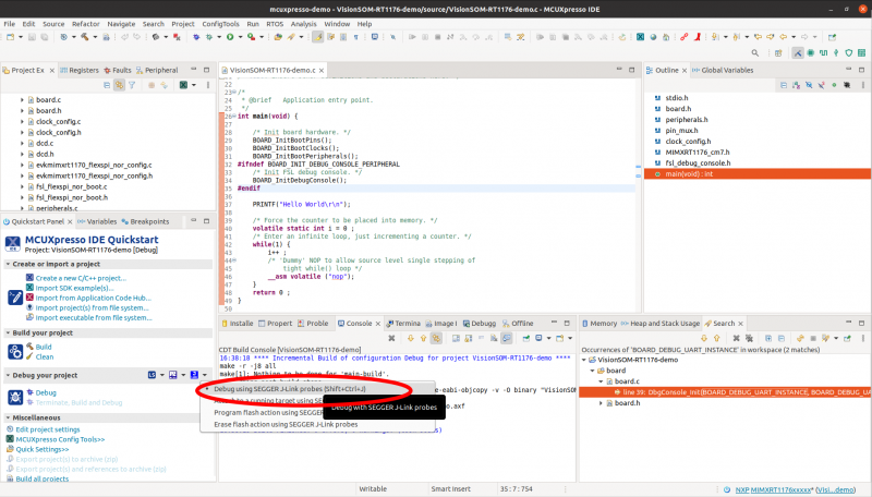
JLink programming can be start using MCUXpresso JLink menu.
FreeRTOS
Finally we can implement FreeRTOS tasks for LED blinking and sending UART messages:
#include <stdio.h>
#include "board.h"
#include "peripherals.h"
#include "pin_mux.h"
#include "clock_config.h"
#include "MIMXRT1176_cm7.h"
#include "fsl_debug_console.h"

#include "FreeRTOS.h"
#include "task.h"

TaskHandle_t ledTaskHandle;
TaskHandle_t uartTaskHandle;

void ledTask(void* param) {

    const TickType_t delayMs = 1000 / portTICK_PERIOD_MS;
    USER_LED_INIT(0);

    while(1) {
        GPIO_PinWrite(BOARD_USER_LED_GPIO, BOARD_USER_LED_GPIO_PIN, 1);
        vTaskDelay(delayMs);
        GPIO_PinWrite(BOARD_USER_LED_GPIO, BOARD_USER_LED_GPIO_PIN, 0);
        vTaskDelay(delayMs);
    }
}

void uartTask(void* param) {

    const TickType_t delayMs = 1000 / portTICK_PERIOD_MS;
    uint8_t i = 0;

    while(1) {
        PRINTF("HELLO TASK %d\r\n", i++);
        vTaskDelay(delayMs);
    }
}

int main(void) {

    BOARD_InitBootPins();
    BOARD_InitBootClocks();
    BOARD_InitBootPeripherals();
#ifndef BOARD_INIT_DEBUG_CONSOLE_PERIPHERAL
    BOARD_InitDebugConsole();
#endif

    xTaskCreate(ledTask,  "LED_TASK",  128, NULL, 1, &ledTaskHandle);
    xTaskCreate(uartTask, "UART_TASK", 128, NULL, 1, &uartTaskHandle);

    vTaskStartScheduler();
    return 0 ;
}
In order to build this example we need to add memory management code to the freertos/freertos-kernel/portable/MemMang directory. We can select one of the files located in the downloaded SDK archive: rtos/freertos/freertos-kernel/portable/MemMang.
The project is now ready to build and run.

