SL-TFT7-TP-600-1024-MIPI Datasheet and Pinout
From SomLabs Wiki

Display module SL-TFT7-TP-600-1024-MIPI Datasheet and Pinout
Contents
General description
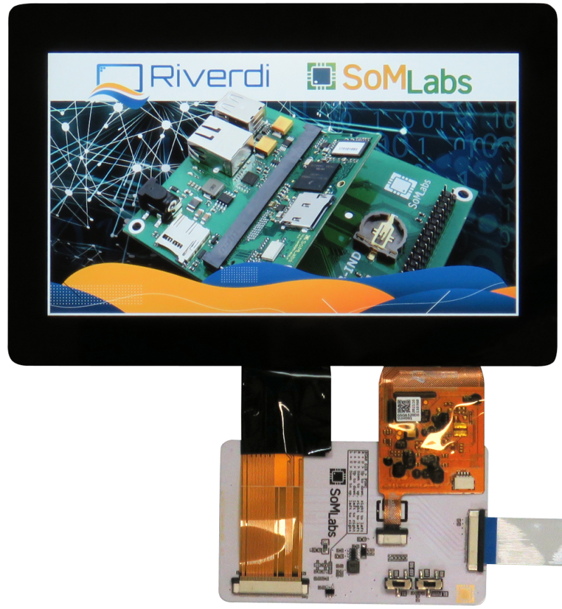
The SL-TFT7-TP-600-1024-MIPI is complete display TFT-LCD (1024x600 pixels) module integrated with capactive touch-panel. Module is powered from +5V @800mA (max.), the data interface is MIPI-DSI + I2C (for touch-panel controller). SL-TFT7-TP-600-1024-MIPI module is equipped with 30-pin flat cable (A-A) and is compatible with selected SoMLabs carrier-boards and video converters.
Features
- Powered by Riverdi RVT70HSMNWC00 TFT module covered with protective glass
- Intergated flexible signal cable
- Display size 7 inches
- Display LCD matrix 1024x600 px
- Capacitive touch-panel + TP controller
- MIPI-DSI interface
- Dual supply +3.3V and +5V (all necessary DC/DC converters are built-in)
- Backlight LEDs built-in
- Compatible with SoMLabs carrier boards equipped with MIPI-DSI video interface
Ordering info
SL-TFT7-TP-600-1024-MIPI v1.1 - FPC 30-pin flat cable (A-A) is included.
Operating ranges
| Parameter | Value | Unit | Comment |
|---|---|---|---|
| Power Supply | |
|
- |
| Current | |
|
Maximum value, depends on displayed picture and backlight intensity |
| Video input voltage | |
|
|
| Touch panel controller IO voltage | |
|
I2C interface, 2.2kΩ pull-up resistor on SDA and SCL lines |
| Environment temperature | oC | - |
Electrical parameters
| Signal name | Parameter | Value | Units | ||
|---|---|---|---|---|---|
| Min. | Typ. | Max. | |||
| VPWR5V | Power Enable Input Voltage | 4.8 | 5.0 | 5.2 | V |
| VPWR3V3 | Power Enable Input Voltage | 3.2 | 3.3 | 3.5 | V |
| IPWR5V | Total Supply Current | 500 | 520 | 600 | mA |
| IPWR3V3 | Total Supply Current | 100 | 135 | 200 | mA |
| VTP | TP Controller IO Voltage | 0 | 3.3 | 3.6 | V |
| VPWREN | Power Enable Input Voltage | 0 | - | 5.0 | V |
| VPWMIN | Power Enable Input Voltage | 0 | - | 3.6 | V |
| fTPI2C | TP Controller I2C Speed | - | - | 400 | kHz |
| RINT | Interrupt Output Pull-up Resistance | - | 10 | - | kΩ |
| RPWREN | Power Enable Pull-up Resistance | - | 10 | - | kΩ |
| RTPI2C | Touch Panel Controller I2C IOs Pull-up Resistance | - | 2.2 | - | kΩ |
| fPWM | Recommended PWM signal frequency | 2 | 2.5 | 4 | kHz |
Pinout
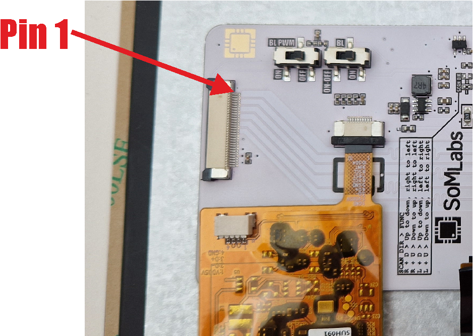
FPC30 connector
| Connector pin | Function name | Description |
|---|---|---|
| 1 | GND | - |
| 2 | MIPI_CLK_p | Data clock positive |
| 3 | MIPI_CLK_n | Data clock negative |
| 4 | GND | - |
| 5 | MIPI_D0_p | Data lane 0 positive |
| 6 | MIPI_D0_n | Data lane 0 negative |
| 7 | GND | - |
| 8 | MIPI_D1_p | Data lane 1 positive |
| 9 | MIPI_D1_n | Data lane 1 negative |
| 10 | GND | - |
| 11 | MIPI_D2_p | Data lane 2 positive |
| 12 | MIPI_D2_n | Data lane 2 negative |
| 13 | GND | - |
| 14 | MIPI_D3_p | Data lane 3 positive |
| 15 | MIPI_D3_n | Data lane 3 negative |
| 16 | GND | - |
| 17 | TP_SCL | Touch panel controller SCL (2.2kOhm pull-up, TTL-LV) |
| 18 | TP_SDA | Touch panel controller SDA (2.2kOhm pull-up, TTL-LV) |
| 19 | GND | - |
| 20 | DISP_CTRL_RES | Optional display controller reset input (10kOhm pull-up, TTL-LV, active low) |
| 21 | TP_INT | Touch panel interrupt (10kOhm pull-up, TTL-LV) |
| 22 | TP_RES | Optional touch-panel controller reset input (10kOhm pull-up, TTL-LV, active low) |
| 23 | GND | - |
| 24 | +3.3V | Power supply for logic (display and touch-panel controllers) |
| 25 | +3.3V | Power supply for logic (display and touch-panel controllers) |
| 26 | +5V | Power supply for backlight |
| 27 | +5V | Power supply for backlight |
| 28 | PWMIN1 | Backlight brightness input (PWM) |
| 29 | PWREN2 | Backlight power enable input (10kOhm pull-down) |
| 30 | GND | - |
Note:
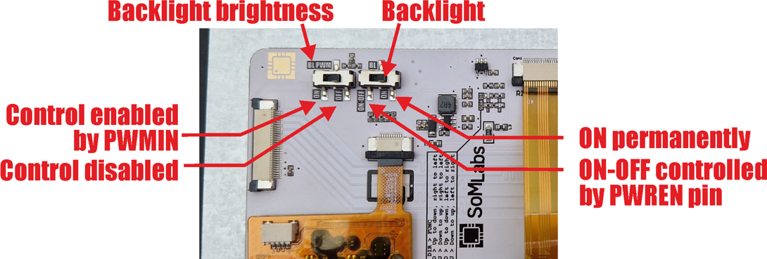
1. PWMIN is external signal input that can be disconnected from DC/DC converter with on-board switch (vide section Switches)
2. PWREN is external signal input that can be disconnected from DC/DC converter with on-board switch (vide section Switches)
Switches
Note:
1. Switch marked BL allows to control on-board backlight DC/DC converter: LEDs can be on permanently (position ON) or cotrolled by logic state of PWREN signal (position ON-OFF, ON if PWREN=1 and OFF if PWREN=0)
2. Switch marked BL PWM allows to change backlight brightness using external PWM signal connected to PWMIN signal. Recommended PWM frequency >=2kHz.
Hardware configuration options
Note:
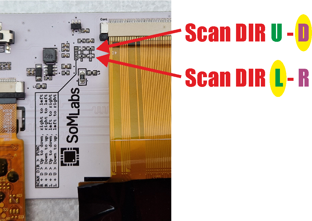
1. In yellow are marked default settings.
2. Marked in green are options available in "left" position of jumpers.
3. Marked in purple are options available in "right" position of jumpers.
4. Details of configurations are available in RVT70HSMNWC00 module datasheet[1].


