Customizing the device tree VisionSOM-STM32MP1
From SomLabs Wiki
Customizing the device tree
This tutorial describes the procedure of customizing the device tree of the meta-somlabs layer used for the OpenSTLinux distribution. The detailed instruction of the system image compilation is available here here. As an example we will add the support of the USART3 of the STM32MP1 as the additional serial port that may be used from the Linux system. We will modify the device configuration files for the DSI display configuration.
The detailed description of the device tree for particular peripherals is available on the ST wiki pages: https://wiki.st.com/stm32mpu/wiki/Category:Device_tree_configuration
Pre-generated device tree files
The device tree files for OpenSTlinux are generated by the STM32CubeMX toot available on the ST website: https://www.st.com/en/development-tools/stm32cubemx.html. In this article the version 5.6.1 of the tool is used.
The base projects generated for the VIsionSOM-STM32MP1 module and VisionCB-STM32MP1-STD board are available for the RGB (VisionSOM) and DSI (VisionSOM-dsi) displays. These projects may be obtained from the following repository (please checkout the proper branch according to your project settings):
git clone https://github.com/SoMLabs/openst-cube-mx.git
Modifying the project using STM32CubeMX
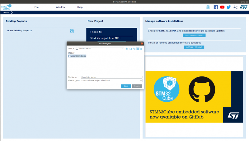
The downloaded projects may be open in the STM32CubeMX tool by loading the ioc file.

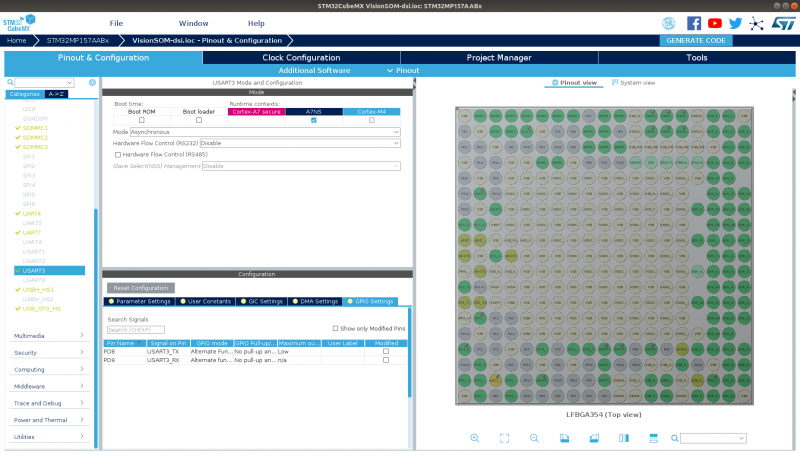
In the application we have access to the GPIO, peripherals and the clock tree configuration. We can add the USART3 port in the Pinout & Configuration section by enabling it for Cortex-A7 non-secure context. In the pinout view (on the right) we can also modify the pin assignment to the selected peripheral. In this example the UART3-TX signal was linked to the PD8 pin.

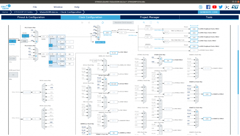
After the peripheral configuration, the clock is automatically enabled, however we can modify the clock source and frequency in the Clock Configuration window. In the example the clock source is PCLK1 (100MHz). In this tool we can also modify the clock sources and frequencies for the whole system.

We can generate the new configuration which will be written in the CA7/DeviceTree/VisionSOM-dsi directory using the GENERATE CODE button in the top-right part of the application window. All subdirectories (kernel, u-boot, tf-a) need to be copied to the meta-somlabs directory overwriting current ones.
Manual changes
After copying new files to the meta-somlabs/mx/visionsom-dsi-mx/ directory some manual changes are required for proper compilation:
Include order
Only in thud version
The includes order in the kernel/stm32mp157a-visionsom-dsi-mx.dts and u-boot/stm32mp157a-visionsom-dsi-mx.dts should be changed to:
#include "stm32mp157c.dtsi"
#include "stm32mp157cab-pinctrl.dtsi"
#include "stm32mp157c-m4-srm.dtsi"
pwm label
Only in thud version
The label of the LED pwm (pwm1) needs to be restored (if used) in the kernel/stm32mp157a-visionsom-dsi-mx.dts and u-boot/stm32mp157a-visionsom-dsi-mx.dts files:
&timers1{
	status = "okay";

	/* USER CODE BEGIN timers1 */

	/delete-property/dmas;
	/delete-property/dma-names;

	/* USER CODE END timers1 */

	pwm1: pwm{
		pinctrl-names = "default", "sleep";
		pinctrl-0 = <&tim1_pwm_pins_mx>;
		pinctrl-1 = <&tim1_pwm_sleep_pins_mx>;
		status = "okay";

		/* USER CODE BEGIN timers1_pwm */
		/* USER CODE END timers1_pwm */
	};
};
Alias
In case of the serial ports a new alias needs to be added to the kernel/stm32mp157a-visionsom-dsi-mx.dts and u-boot/stm32mp157a-visionsom-dsi-mx.dts files:
aliases {
ethernet0 = ðernet0;
serial0 = &uart4;
serial1 = &uart7;
serial2 = &usart3;
mmc0 = &sdmmc1;
mmc1 = &sdmmc2;
};
RGB panel u-boot configuration
If the RGB panel is used, the u-boot configuration in the u-boot/stm32mp157a-visionsom-dsi-mx.dts file needs to be restored according to the original version:
	panel {
		status = "okay";
		u-boot,dm-pre-reloc;
		compatible = "simple-panel";
		backlight = <&backlight>;
				power-supply = <&vdd>;
		enable-gpios = <&gpioa 1 GPIO_ACTIVE_LOW>;

		display-timings {
						timing0: timing0 {
						clock-frequency = <33300000>;
							hactive = <800>;
							vactive = <480>;
							hfront-porch = <210>;
							hback-porch = <46>;
							hsync-len = <46>;
							vback-porch = <23>;
							vfront-porch = <22>;
							vsync-len = <23>;
							hsync-active = <0>;
							vsync-active = <0>;
							de-active = <0>;
							pixelclk-active = <1>;

			};

		};
	};
<dc{
pinctrl-names = "default", "sleep";
pinctrl-0 = <<dc_pins_mx>;
pinctrl-1 = <<dc_sleep_pins_mx>;
status = "okay";
/* USER CODE BEGIN ltdc */
u-boot,dm-pre-reloc;
/* USER CODE END ltdc */
};
When the new dts files are ready we can rebuilt and install the whole system or just the kernel sources (if only the kernel/stm32mp157a-visionsom-dsi-mx.dts file was modified):
bitbake linux-stm32mp
The dtb files are located in the tmp-glibc/deploy/images/stm32mp157a-visionsom-dsi-mx directory (some of them are symbolic links):
We can copy the correct dtb file to the bootfs partition and replace the existing one.
In this example, after rebuilding the system a new device will be available:
/dev/ttySTM3