How to create and run the first application on the StarSOM-STM32H757
From SomLabs Wiki
How to create and run the first application on the StarSOM-STM32H757
This article describes how to create and run first application on the StarSOM-STM32H757 module. The application uses LED and UART peripherals and is executed from the internal Flash memory.
Requirements
This demo requires the following hardware modules:
- StarSOM-STM32H757
- StarCB-STM32H757-STD carrier board
The application was created using:
- STM32CubeIDE Version: 1.17.0.
Creating a new project
Select File -> New -> STM32 Project and choose STM32H757XIH6 microcontroller:
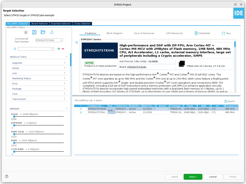
In the next window enter the project name and finish the creator.
Confirm creating default MPU configuration and code generation.
Clocks configuration
The StarSOM-STM32H757 module provides external clock sources that can be used as HSE and LSE clock in the project. Both clocks need to be enabled in the RCC peripheral in Device Configuration Tool:
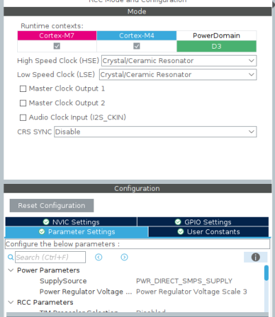
In the same window the power supply source should be set to PWR_DIRECT_SMPS_SUPPLY.
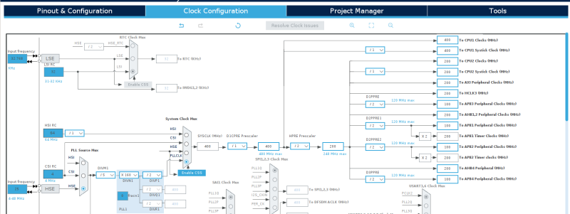
Using embedded SMPS limits the M7 Core clock to 400MHz. The example clock tree is shown below:
GPIO configuration
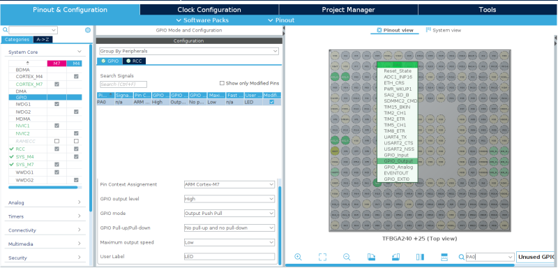
This example requires one GPIO line for LED control. It can be configured from the Pinout view perspective. Each GPIO line needs also assigned context CM7 or CM4.
UART configuration
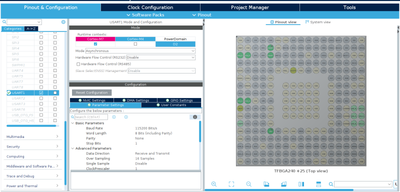
On StarCB-STM32H757-STD board, the USART1 pins (PB6/PB7) are connected to ST-Link virtual COM port. USART1 peripheral can be configured by assigning it to a CM7 context and setting asynchronous mode. The remaining options should remain in default state. The PB6 and PB7 are configured automatically.
Modifying the generated code
After saving all changes in the Device Generation Tool, the application code can be generated. This example needs the following changes in it:
Disabling hardware semaphore synchronization
The default code contains synchronization between CM4 and CM7 cores implemented using the hardware semaphore. In this example only a single CM7 core is used so the synchronization part in the USER CODE BEGIN Boot_Mode_Sequence_1 and USER CODE BEGIN Boot_Mode_Sequence_2 section in main function should be removed:
/* USER CODE BEGIN Boot_Mode_Sequence_1 */
  /* Wait until CPU2 boots and enters in stop mode or timeout*/
  //timeout = 0xFFFF;
  //while((__HAL_RCC_GET_FLAG(RCC_FLAG_D2CKRDY) != RESET) && (timeout-- > 0));
  //if ( timeout < 0 )
  //{
  //Error_Handler();
 // }
/* USER CODE END Boot_Mode_Sequence_1 */
/* USER CODE BEGIN Boot_Mode_Sequence_2 */
/* When system initialization is finished, Cortex-M7 will release Cortex-M4 by means of
HSEM notification */
/*HW semaphore Clock enable*/
//__HAL_RCC_HSEM_CLK_ENABLE();
/*Take HSEM */
//HAL_HSEM_FastTake(HSEM_ID_0);
/*Release HSEM in order to notify the CPU2(CM4)*/
//HAL_HSEM_Release(HSEM_ID_0,0);
/* wait until CPU2 wakes up from stop mode */
//timeout = 0xFFFF;
//while((__HAL_RCC_GET_FLAG(RCC_FLAG_D2CKRDY) == RESET) && (timeout-- > 0));
//if ( timeout < 0 )
//{
//Error_Handler();
//}
/* USER CODE END Boot_Mode_Sequence_2 */
Disabling LDO supply support
Despite setting the SMPS supply in the Device Configuration Tool, the LDO support is till enabled by USE_PWR_LDO_SUPPLY macro in project settings. This macro is added during each code generation, but can be disabled in Common/Src/system_stm32h7xx_dualcore_boot_cm4_cm7.c file with #undef instruction:
#if defined(USE_PWR_LDO_SUPPLY)
#undef USE_PWR_LDO_SUPPLY
#endif
Implementing main loop
The example application periodically changes the PA0 LED state and sends the string to USART1 port.
  while (1)
  {
    /* USER CODE END WHILE */
    HAL_GPIO_TogglePin(LED_GPIO_Port, LED_Pin);
    HAL_UART_Transmit(&huart1, "Hello StarSOM-STM32H757\r\n", 25, 100);
    HAL_Delay(1000);
    /* USER CODE BEGIN 3 */
  }
Flashing the application
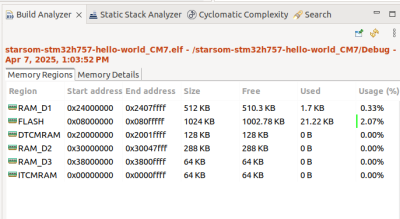
The application is placed by default in the internal Flash memory. It can be verified with Build Analyzed tool:
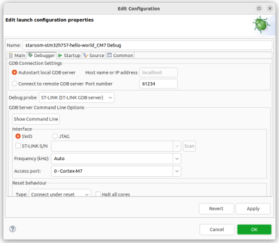
In order to flash it using the ST-LINK on StarCB-STM32H757-STD carrier board, select Run -> Debug As -> STM32 C/C++ Application and make sure that the SWD is selected as Debugger interface:
